Stream Deck Classic
Introduction
The Stream Deck Classic Family are 15-Key USB 2.0-compliant input devices featuring a 3×5 grid of keys atop a single LCD screen. They communicate with the host via the USB HID protocol, enabling key event reporting, image upload, and device configuration.
For all concepts, data types, report structures, and shared commands refer to the General Reference page. This page documents only what is specific to the 15-key family.
Devices Overview
Summary
| Name | Model | VID | PID | Capabilities |
|---|---|---|---|---|
| Stream Deck 15-Key Module | 20GBA9901 | 0x0FD9 | 0x00B9 | 15 Key Layout |
| Stream Deck 2019 | 20GAA9902 | 0x0FD9 | 0x006D | 15 Key Layout |
| Stream Deck Mk.2 | 20GBA9901 | 0x0FD9 | 0x0080 | 15 Key Layout |
| Stream Deck Mk.2 (Scissor Keys) | 20GBL9901 | 0x0FD9 | 0x00A5 | 15 Key Layout |
All models in this family share the same HID command set and 15-key layout. Adjust the PID when targeting a specific model.
The Stream Deck with PID 0x0060 is not supported by this protocol. This device is part of the first models released in 2017 and uses its own protocol, which will be documented in the future.
Capabilities & Physical Characteristics
15 Key Layout
| Entity | Property |
|---|---|
| LCD Image | 480 × 272 px (low DPI) |
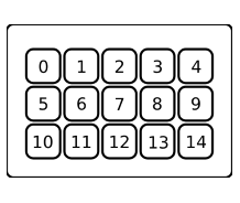
| Keys matrix | 5 × 3 |
| Key Image | 72 × 72 px |
Keypad Keys Index Layout
Unit Pixel Layout
Command Descriptions
Output Reports
The Report ID of output reports is 0x02. When the payload does not fit into a single report, it must be split into multiple chunks.
Update Key Image
Uploads an image for a specific key.
| Offset | Type | Note |
|---|---|---|
| + 0x00 | Output Report | Report ID: 0x02, Command: 0x07 |
| + 0x02 | UINT8 | Key Index |
| + 0x03 | UINT8 | Transfer is Done flag (0x01 = last chunk) |
| + 0x04 | UINT16 | Chunk Contents Size |
| + 0x06 | UINT16 | Chunk Index (zero-based) |
| + 0x08 | UINT8[] | Chunk Data |
Update Full Screen Image
Uploads an image for the entire LCD.
| Offset | Type | Note |
|---|---|---|
| + 0x00 | Output Report | Report ID: 0x02, Command: 0x08 |
| + 0x02 | UINT8 | Reserved |
| + 0x03 | UINT8 | Transfer is Done flag (0x01 = last chunk) |
| + 0x04 | UINT16 | Chunk Contents Size |
| + 0x06 | UINT16 | Chunk Index (zero-based) |
| + 0x08 | UINT8[] | Chunk Data |
Update Background
Uploads an image to be stored as a background at a given index.
| Offset | Type | Note |
|---|---|---|
| + 0x00 | Output Report | Report ID: 0x02, Command: 0x0D |
| + 0x02 | UINT8 | Background Index |
| + 0x03 | UINT8 | Transfer is Done flag (0x01 = last chunk) |
| + 0x04 | UINT16 | Chunk Index (zero-based) |
| + 0x06 | UINT16 | Chunk Contents Size |
| + 0x08 | UINT8[] | Chunk Data |
Device Setup & Communication
Uploading Images
Key Image
- Prepare a
72 × 72 pximage. - Rotate the image
180°before upload (required for all models in this family). - Export in JPEG format.
- Send using the Update Key Image command sequence.
Full LCD Image
- Prepare a
480 × 272 pximage. - Rotate the image
180°before upload (required for all models in this family). - Export in JPEG format.
- Send using the Update Full Screen Image command sequence.
INDEX
Input Reports Reference
| Report ID | Command | Description |
|---|---|---|
0x01 | 0x00 | Key press state change |
Output Reports Reference
| Report ID | Command | Description |
|---|---|---|
0x02 | 0x07 | Update Key Image |
0x02 | 0x08 | Update Full Screen Image |
0x02 | 0x0D | Update Background |
Feature Reports Reference
Setter Feature Reports
| Report ID | Command | Description |
|---|---|---|
0x03 | 0x02 | Show Logo |
0x03 | 0x05 | Fill LCD with Color |
0x03 | 0x06 | Fill Key with Color |
0x03 | 0x08 | Set Backlight Brightness |
0x03 | 0x0D | Set Sleep Mode Duration |
Getter Feature Reports
| Report ID | Command | Description |
|---|---|---|
0x04 | Get Firmware Version (LD) | |
0x05 | Get Firmware Version (AP2) | |
0x06 | Get Unit Serial Number | |
0x07 | Get Firmware Version (AP1) | |
0x08 | Get Unit Information | |
0x0A | Get Sleep Mode Duration |